General
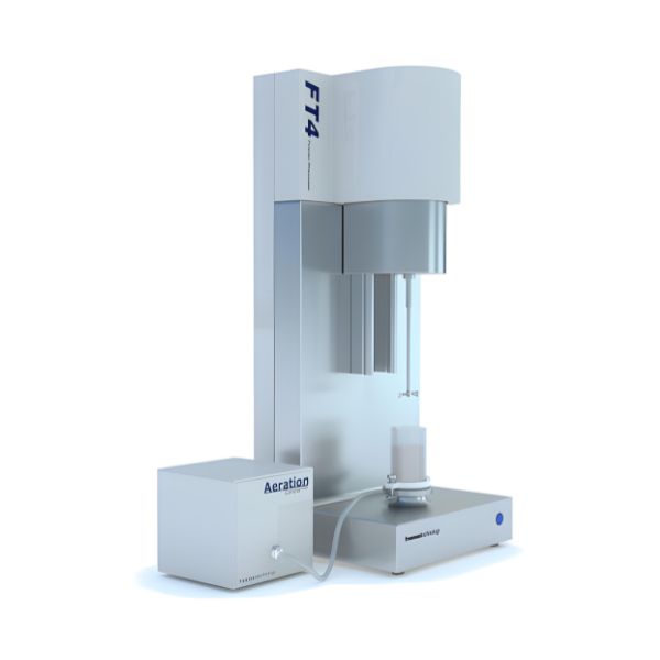
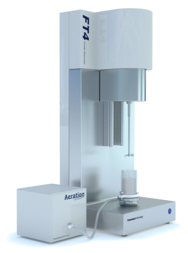
The FT4 Powder Rheometer® – a universal powder flow tester for measuring powder flow properties and powder behaviour.
The FT4 was designed with one purpose in mind – to characterise the rheology of powders, or powder flow properties. This remains a primary function today, but the instrument, accessories and methodologies have been continuously developed to the point where the FT4 is now considered a universal powder flow tester. It differs from other powder testers in many ways but when assessing industrial value, three features are critical:
Features:
- The ability to simulate powder processing conditions, by testing samples in a consolidated, moderately stressed, aerated, or fluidized state.
- The application of multi-faceted powder characterization to assess dynamic flow, bulk, and shear properties to construct the most comprehensive understanding of how a powder behaves.
- Unparalleled sensitivity enables the differentiation of powders that other testers classify as identical.
- Fully automated test programs and data analysis
- Conditioning mode provides unparalleled repeatability
- Range of sample size, 10ml to 160ml (in addition a 1ml Shear Cell can be selected for limited sample size)
How it works
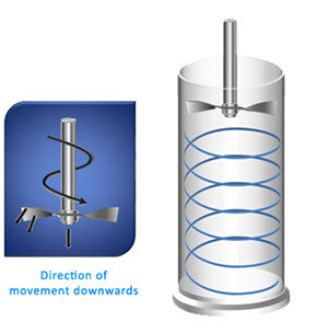
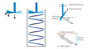
The FT4 employs unique technology for measuring the resistance of the powder to flow, whilst the powder is in motion. A precision ‘blade’ is rotated and moved downwards through the powder to establish a precise flow pattern. This causes many thousands of particles to interact, or flow relative to one another, and the resistance experienced by the blade represents the difficulty of this relative particle movement, or the bulk flow properties.
Excellent reproducibility is achieved by moving the blade in a precise and reliable way. The advanced control systems of the FT4 accurately set the rotational and vertical speeds of the blade, which defines the Helix Angle and Tip Speed.
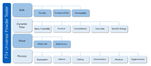
FT4 Methodologies
The FT4 is a truly universal powder flow tester, with four categories of methodologies, defined as Bulk, Dynamic Flow, Shear (under ASTM D7891) and Process.
Proven Applications
The FT4 has applications in all powder processing industries, including Pharmaceuticals, Fine Chemicals, Food, Cosmetics, Toners, Metals, Ceramics, Plastics, Powder Coatings, Cements, and Additive Manufacturing. Applications extend to:
- Wet Granulation End Point & Scale Up
- Flow Additive Selection & Optimization
- Compact Hardness & Payoff
Whether your objective is to optimise a formulation in a development environment, predict in-process performance, understand batch differences, or to ensure the quality of raw materials or intermediates, the FT4 will provide valuable and unique information that will help you address your powder flow challenges.
Versatility
The Need For Versatility
As we have seen in previous sections, powder flow properties are complex and cannot be quantified by a single number. Flowability must be considered in relation to the conditions imposed by the process and application. Powders may exhibit “good” flow if loosely packed, but “bad” flow after consolidation. Some powders may flow well as long as flow rates are relatively high, however they may stop flowing when moved more slowly.
The FT4 has been designed to allow the effect of each of these External Variables to be investigated. By closely simulating process conditions in the measurement cell, the powder’s response to each variable can be quantified.
External variables include:
Methodology
Dynamic Methodology
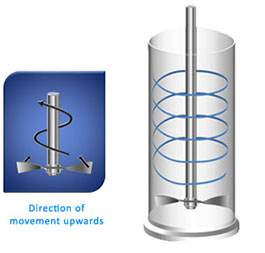
The FT4 employs patented technology for measuring the resistance of the powder to flow, whilst the powder is in motion. A precision ‘blade’, or impeller, is rotated and moved downwards and upwards through the powder to establish a precise flow pattern. This causes many thousands of particles to interact, or flow relative to one another, and the resistance experienced by the blade represents the difficulty of this relative particle movement, or the bulk flow properties. The more the particles resist motion and the harder it is to get the powder to flow, the more difficult it is to move the blade.
As the blade moves through the sample, the FT4 measures both rotational and vertical resistances, in the form of Torque and Force respectively. It is important to capture both signals as it is the composite of these two values that quantifies the powder’s total resistance to flow.
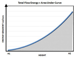
Using the calculation of Work Done, it is possible to represent both the Torque and Force signals as a Total Flow Energy, the energy required to move the blade through the sample from the top to the bottom of the powder column. However, because the values of torque and force are constantly changing, it is necessary to calculate the energy for each small distance travelled. This is the calculation of Energy Gradient, the energy measured for each millimetre of blade travel, expressed in mJ/mm.
- Work Done = Energy = (Resistance x Distance travelled).
- Where ‘Resistance’ is the combined Torque and Force
- Energy Gradient = Energy per mm of blade travel
Calculating the area under the Energy Gradient curve provides the Total Flow Energy, representing the powder’s resistance to being made to flow in a dynamic state.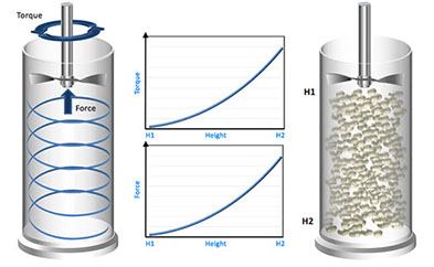
Powder flow
Confined and Unconfined Powder Flow
Two types of powder flow patterns are typically employed for quantifying flowability:
Forced (or confined) Flow
A measure of the powder’s flowability when forced to flow, such as through a screw feeder or in an active feed frame. This property is defined as the Basic Flowability Energy, BFE, and is measured during the downward blade movement. The powder is confined by the closed bottom end of the test vessel.
Low Stress (unconfined) Flow
A measure of the powder’s flowability when unconfined, such as during low-stress filling, or low-shear blending. This property is defined as the Specific Energy, SE. In this measurement, the resistance to flow is measured as the blade traverses from the bottom of the vessel to the top. As there is no solid surface at the top of the vessel preventing the powder from dilating and moving upwards, the powder is unconfined during this test.
The regimes of confined and unconfined flow are very different so it is important, when correlating data with process performance, to identify which regime is most representative of the process being considered.
Conditioning
Conditioning
Anyone who has worked with powders will know how easily they change their density, just as a result of handling them. Tip them from a beaker and they aerate, or tap the beaker on the bench and observe a reduction in volume as the powder becomes compacted.
These changes in density are a consequence of changes in the stress applied to the powder. As discussed previously, variation in stress level is likely to have a major impact on how the powder behaves, within a process or application, but also during a measurement. It is therefore essential to ensure the powder is prepared for any test by first establishing a uniform stress in the powder bed and eliminating pockets of air or localised compaction.
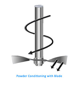
This preparation step is called Conditioning and is a simple, but effective mechanical process designed to prepare the sample for the following measurement. Utilising the same patented technology that is used in the dynamic methodologies (see previous pages), the Conditioning process involves gentle displacement of the whole sample in order to loosen and slightly aerate the powder. The aim is to disturb and gently drop each particle in order to construct a homogenously packed powder bed, removing any precompaction or excess air and ensuring the results from the following test are independent of how the operator handles the powder and places it into the testing vessel.
A conditioning cycle is usually completed before every test to remove the variability introduced by the operator during loading of the sample, and any residual compaction from previous tests. The exception is where an intentionally consolidated sample is being evaluated, in which case conditioning is not employed.
Variables
Using Dynamic Methods to Quantify the Effects of External Variables
The Basic Flowability Energy is a measure of a powder’s flow properties when the powder is in a loosely packed state (following conditioning). Using this same dynamic methodology, it is possible to quantify how powder flow properties change when it is subjected to any of the external variables defined in the previous sections.
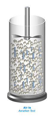
Aeration
In order to quantify the influence of air, a controlled air supply can be introduced through a porous mesh at the base of the powder column. This method is not just to simulate processes and applications where air is intentionally introduced into the powder, such as during conveying, drying and in dry powder inhaler applications, but importantly to explore the cohesive forces that exist between particles.
Cohesive forces are notoriously difficult to measure, but can now be accurately and directly quantified by assessing how aeration changes the flow properties of the bulk powder. Cohesive forces are a combination of Van der Waal’s and electrostatics and tend to “bond” particles together. The introduction of air to the powder column attempts to separate adjacent particles and overcome these cohesive forces. If the forces are weak, each particle will become mechanically separated from its neighbor and the powder will become fluidized. The measured resistance to flow, the Aerated Energy, AE quantifies the strength of the cohesive forces.
For powders with weak cohesive forces, the Aerated Energy tends toward zero as the powder becomes fully aerated. Powders with moderate to high cohesion will exhibit a reduction in flow energy when aerated but to a much lesser extent. In these cohesive powders, the tensile forces are too strong for the air to overcome and the particles do not separate. Instead, a channel is established in the powder through which the air passes, and the corresponding Aerated Energy remains relatively high, even at high air velocities.
Contrasting Basic Flowability Energy with Aerated Energy results in the Aeration Ratio, AR, where:
- Aeration Ratioxx = Basic Flowability Energy / Aerated Energyxx = BFE / Aexx
- where ‘xx’ defines the air velocity in mm/s at which the Aerated Energy measurement is taken.
- The Aeration Ratio is a measure of the powder’s sensitivity to aeration
Bulk Properties
Bulk Properties
Bulk properties are not a direct measurement of flowability or shear, but nevertheless influence process performance and product attributes. The FT4 Powder Rheometer® measures typically three types of bulk powder properties:
Density
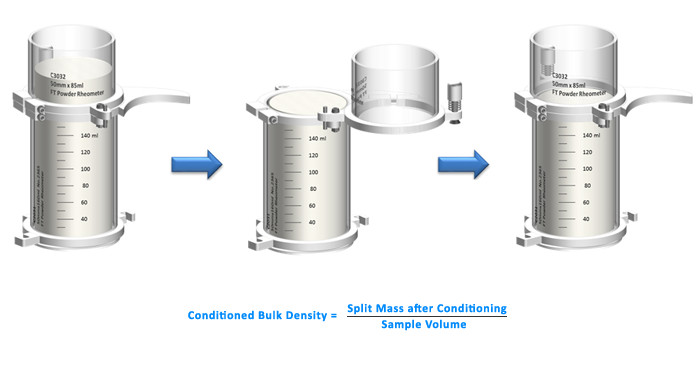
Density defines the relationship between mass and volume. In principle this seems a simple concept, but the nature of powders means that their packing structure can change easily and significantly. Therefore when defining density, it is essential to ensure the packing state is well known and can be reproduced. This is achieved on the FT4 using a Conditioning cycle. When combined with other features such as the built in balance and Split Vessels, which allow a precise volume to be attained, the Conditioned Bulk Density can be measured with unprecedented levels of accuracy.
Compressibility
The measurement of Compressibility is achieved by applying increasing levels of compressive force with a piston to a conditioned powder and measuring the change in volume as a function of the applied load. The Vented Piston ensures that air trapped within the powder is able to readily escape, and the high resolution of the position measurement system allows for precise definition of Compressibility, expressed as a percentage change in volume for a given applied normal stress.
It is possible to apply a number of mathematical models to this data, but it is important to consider that in doing so, trends may be exaggerated or reduced. Fitting Mohr stress circles to the yield locus identifies the Major Principle Stress (Sigma 1) and Unconfined Yield Strength (Sigma c), and the ratio of the former to the latter quantifies the Flow Function, FF. Flow Function is a parameter commonly used to rank flowability, with values below 4 denoting poor flow and above 10, good flow.
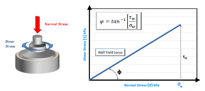
Wall Friction
The Wall Friction test provides a measurement of the sliding resistance between the powder and the surface of the process equipment. This is particularly important for understanding discharge behaviour from hoppers, continuity of flow in transfer chutes and tablet ejection forces. It is also useful when investigating whether a powder will adhere to the wall of process equipment and various other surfaces, such as the inside of sachets, capsules and other packaging material.
The measurement principle is very similar to the shear cell test, but rather than shearing powder against powder, in this test a coupon of material representing the process equipment wall is sheared against the powder in question. The FT4 Wall Friction accessory allows for a range of coupons to be investigated, and bespoke surfaces can be manufactured if required.
Data is typically represented as a plot of shear stress against normal stress, allowing the determination of Wall Friction Angle (phi). The greater the wall friction angle, the higher the resistance between the powder and wall coupon.
This data can be utilised in specific studies, as outlined above, but is also required as part of a hopper design exercise.
Hopper Design
Hoppers are used extensively throughout the processing environment and whilst they are often considered to be simple systems, they are responsible for causing a great deal of process interruption and product quality issues.
If a powder possesses properties that are not optimised for the hopper geometry and equipment surface, then flow from the hopper may be variable or even none existent. However, since the pioneering work carried out by Andrew Jenike in the mid-twentieth century, it has been possible to utilize data from shear cell and wall friction tests to calculate the critical hopper dimensions to ensure good flow.
The FT4 comes with fully automated hopper design software, which takes the results directly from shear cell and wall friction tests and runs the data through the hopper design algorithms. The result is a fully automated hopper design exercise in less than 3 hours.
Today, this hopper design process remains one of the very few fundamental approaches to equipment design, based on an understanding of material properties and the stress regime within the equipment. Unfortunately, such an approach is not available for mixers, feeders, conveyors, dryers, compression processes or any of the other unit operations routinely used in powder processing.
Please contact us for more information on the hopper design process, if required.